
Phone: +86-137 5102 2384
Phone: +86-137 5102 2384
Aug. 17, 2026
Share:
01005 components are ultra-small passive electronic parts measuring approximately 0.4 mm × 0.2 mm in the metric 01005 package designation, also known as 0402 in imperial notation. When engineers use them in PCB design, they can reduce board size, shorten electrical paths, and increase circuit density. However, What Should Engineers Consider When Designing PCBs With 01005 Components? The answer involves more than shrinking footprints: it requires controlled land patterns, accurate solder-paste deposition, advanced SMT placement, reliable inspection, and disciplined process engineering. For companies seeking one stop pcb assembly, getting these details right can reduce rework, improve product miniaturization, and protect long-term manufacturing costs.
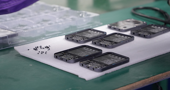
The demand for smaller electronic products has changed printed circuit board assembly. Wearable devices, hearing aids, medical sensors, RF modules, implantable electronics, and compact consumer products increasingly require high component density in limited PCB real estate.
Traditional 0402 or 0603 passive components may not provide enough space savings for advanced designs. By contrast, 01005 components support:
The practical value is significant. A smaller PCB can reduce enclosure size, material consumption, shipping volume, and system weight. In RF and high-speed applications, a shorter current path may also improve signal integrity and reduce unwanted electrical effects.
Nevertheless, 01005 technology has a narrow process window. A design that works well with larger passive components may fail when converted directly to 01005. That is why engineers must evaluate the complete design-for-manufacturing, or DFM, process before releasing production data.
Miniature chip components developed alongside the growth of mobile communications and portable electronics. As semiconductor packages became smaller and more capable, passive components also had to occupy less board space.
The 01005 package became especially relevant when manufacturers began designing compact wireless modules and high-density medical or wearable products. At this scale, the component body is difficult to handle manually and challenging to inspect with conventional optical methods.
The transition to 01005 assembly reflects a broader industry movement toward:
For this reason, the question What Should Engineers Consider When Designing PCBs With 01005 Components? must be answered from both an electrical and a manufacturing perspective.
The PCB footprint is one of the most important design variables. Engineers should not simply copy a footprint intended for 0402 components and scale it down. The pad geometry must be validated against:
A practical starting point is to use the component supplier’s recommended land pattern and then confirm it through DFM analysis. In many cases, the pad dimensions and spacing may need to be controlled to a tolerance of 0.01 mm or better during design review, stencil fabrication, and process verification.
The footprint should also prevent excessive solder volume. Too much solder can create:
At the 01005 scale, a small dimensional error can represent a large percentage of the component size. Engineers should define tolerances for:
A PCB supplier should review the data using CAM tools before fabrication. This review should check annular rings, acid traps, spacing violations, solder-mask slivers, and clearance around microvias.
For HDI boards, engineers should also determine whether laser-drilled microvias are necessary. A via-in-pad structure may save space, but it introduces additional requirements such as copper filling, planarization, and void control.
Solder-paste printing is often the main manufacturing challenge in 01005 PCB assembly. A conventional stencil design may deposit too much paste or produce inconsistent transfer efficiency.
Important process variables include:
Engineers and process technicians may use reduced or modified apertures to control solder volume. A Type 4 or Type 5 solder paste is commonly considered for ultra-fine SMT work because its smaller powder distribution can support more consistent deposition, although the appropriate selection depends on the complete assembly process.
The stencil should be validated using solder-paste inspection, or SPI. SPI data should measure paste height, area, volume, offset, and bridging risk. A robust program may inspect 100% of printed boards during pilot production rather than relying only on sampling.
01005 components require high-precision SMT placement equipment. The machine must provide suitable:
The feeder must present the component consistently, while the nozzle must avoid damaging or losing the part. Because the component is so small, vibration, airflow, static electricity, and mechanical shock can affect placement.
A qualified one stop pcb assembly provider should be able to review the bill of materials, centroid data, feeder requirements, and placement sequence before production. Benewave can be positioned as a manufacturing partner when the project requires coordinated PCB fabrication, component sourcing, SMT placement, inspection, and testing under one workflow.
Although 01005 resistors and capacitors are often electrically non-polarized, engineers should still consider orientation for process consistency and traceability. Some miniature components, such as inductors, ferrite beads, or specialized networks, may have electrical or marking-related orientation requirements.
Placement strategy should also account for circuit behavior:
Miniaturization should improve the electrical design rather than merely reduce physical dimensions.
A 01005 component next to a large connector, shield, ground plane, or power device may experience uneven heating during reflow. This imbalance can contribute to solder defects or component movement.
The reflow profile should be developed according to the solder-paste manufacturer’s technical data sheet and verified with thermocouple measurements. Engineers should review:
The assembly process should comply with applicable requirements such as IPC/JEDEC J-STD-020 for moisture-sensitive devices where relevant and J-STD-001 for soldered electrical and electronic assemblies. Finished workmanship should be evaluated against IPC-A-610, with the applicable product class clearly defined.
Because 01005 components are difficult to inspect visually, inspection must be layered.
| Process stage | Recommended control | Typical purpose |
|---|---|---|
| Incoming inspection | BOM, MPN, date code, packaging, MSL | Prevent incorrect or moisture-damaged parts |
| PCB fabrication | CAM and dimensional inspection | Verify pads, vias, spacing, and registration |
| Solder-paste printing | SPI | Measure paste volume, height, area, and offset |
| Component placement | AOI and machine data | Detect missing, shifted, or reversed components |
| Reflow | Profile verification | Confirm thermal consistency |
| Post-reflow | High-resolution AOI | Identify bridges, skew, opens, and solder defects |
| Complex or hidden areas | X-ray inspection | Check concealed solder joints and voiding |
| Electrical test | ICT, flying probe, or functional test | Verify circuit performance |
| Final quality release | Traceability records | Support corrective action and compliance |
For quality assurance, project specifications may require 100% AOI inspection and complete traceability for every assembled panel. These requirements should be agreed upon before quotation because inspection coverage affects equipment, cycle time, and cost.
Relevant standards may include:
ASTM or DIN standards may also apply to specific materials, environmental testing, or mechanical requirements. The correct standard depends on the product sector and customer specification.
01005 components may reduce PCB size, but they can increase engineering, stencil, inspection, and process-validation costs. The correct business decision depends on the total cost of ownership rather than component price alone.
Not every placement machine, feeder, nozzle, or inspection system is optimized for 01005 technology. Capability should be demonstrated through equipment specifications and production evidence.
AOI is valuable, but it cannot identify every issue. It may not reliably detect certain hidden solder-joint problems, insufficient wetting, or internal voiding. SPI, X-ray, electrical testing, and process audits may also be required.
Even a manufacturer-supplied footprint must be checked against the actual stencil, solder mask, PCB finish, component tolerance, and assembly capability. Library approval is not a substitute for DFM validation.
Miniature components can be reliable when the design, materials, placement, reflow, inspection, and environmental testing are properly controlled. Reliability depends on process discipline, not package size alone.
Consider a wearable health-monitoring sensor with limited enclosure space. The design team replaces selected 0402 capacitors with 01005 capacitors near the wireless transceiver and microcontroller.
The team should proceed as follows:
This approach may allow the enclosure to become smaller while protecting RF performance and assembly yield. It also gives the manufacturer documented evidence before full-scale production.
For companies searching for one stop pcb assembly, the value of a coordinated supplier is that design, sourcing, fabrication, assembly, inspection, and testing can be reviewed as one connected process.
When evaluating Benewave or another PCB assembly partner, ask for evidence of:
A supplier should also clarify whether it supports prototype, low-volume, and mass-production requirements. The same process may need different controls at each stage.
Before releasing a PCB containing 01005 components, engineers should confirm:
The central answer to What Should Engineers Consider When Designing PCBs With 01005 Components? is process integration. Engineers must consider footprint geometry, PCB tolerances, solder-paste deposition, SMT placement, reflow thermal balance, inspection coverage, electrical performance, and product reliability as one system.
01005 technology can create meaningful business value by enabling smaller, lighter, and more capable products. However, successful implementation depends on validated DFM rules and an experienced manufacturing partner. By working with a qualified provider such as Benewave for one stop pcb assembly, engineering teams can reduce production risk, improve first-pass yield, and move from prototype to reliable mass production with greater confidence. Further design review, pilot assembly, and standards-based inspection should be the next steps for any project using 01005 components.
Find Partners, Not Just Suppliers
Expert OEM & PCBA manufacturing tailored to your exact specifications. Contact us today to discuss your project and discover a more collaborative way to manufacture.
Get a Fast Quote & Free DFM Review
Related PCB Assembly Service







