
Phone: +86-137 5102 2384
Phone: +86-137 5102 2384
Jun. 30, 2026
Share:
The smart home and IoT market is projected to exceed 22 billion connected devices by the end of 2026, with analysts forecasting nearly 39 billion by 2030. Every one of these devices—whether a smart thermostat, a wearable health tracker, or a mesh-networked security sensor—depends on a printed circuit board assembly (PCBA) that must simultaneously handle wireless connectivity, ultra-low-power operation, mixed-signal processing, and long-term reliability, often within a footprint smaller than a matchbook.
Unlike traditional consumer electronics, IoT PCBAs operate under severe constraints: they must maintain reliable RF communication in densely packed enclosures, survive on coin-cell batteries for years, and comply with strict regulatory frameworks—all while being produced at massive scale. This article examines the specific technical requirements, design considerations, and manufacturing processes that distinguish professional IoT PCB assembly from conventional electronics production.
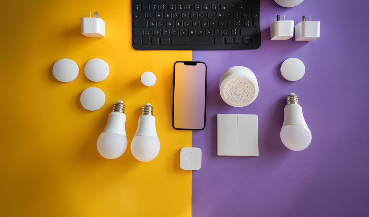
Smart home devices demand compact form factors, pushing PCBs toward high-density interconnect (HDI) technology and multilayer stackups. A typical IoT PCB may use 0.1 mm trace widths, 0201 or even 01005 passive components, and fine-pitch BGAs or chip-scale packages (CSPs). This density creates routing congestion and requires advanced SMT placement accuracy (typically ±25 µm at 3σ) to avoid solder bridging or tombstoning.
IoT boards integrate digital MCUs, analog sensors, RF transceivers, and switching power regulators on a single small PCB. Without careful zoning, high-speed digital clocks and DC-DC converters inject noise into sensitive RF front-ends and analog sensor inputs. Proper PCB assembly begins with design-for-manufacturing (DFM) discipline: separating digital, analog, and RF domains, maintaining solid ground planes, and controlling return paths to prevent crosstalk and EMI.
Most smart home devices rely on Wi-Fi, Bluetooth, Zigbee, Thread, or Matter protocols. Integrating these wireless modules demands:
Impedance-Controlled Routing: RF traces must maintain 50Ω characteristic impedance with consistent stackup dielectric thickness and trace geometry.
Antenna Keep-Out Zones: Embedded PCB antennas or ceramic chip antennas require clear copper-free areas and must be positioned away from batteries, metal shields, and noisy switching regulators.
Multi-Protocol Coexistence: Devices supporting simultaneous Wi-Fi and Bluetooth (e.g., ESP32-C6 modules) require careful isolation to prevent desensitization and ensure stable coexistence.
For most smart home applications, standard FR-4 (Tg 130–150°C) is sufficient because operating temperatures are moderate. However, devices with high LED thermal loads or outdoor exposure may require High-Tg FR-4 (Tg ≥170°C) or metal-core PCBs for thermal management. For high-frequency 5 GHz Wi-Fi or 6 GHz applications, low-loss materials (lower Df) may be necessary to maintain signal integrity.
IoT designs often use pre-certified wireless modules (e.g., Nordic nRF52/54 series, Silicon Labs EFR32, Espressif ESP32) rather than discrete RF chips to reduce development risk and accelerate certification. Assembly houses must:
Source modules exclusively through authorized distributors to prevent counterfeit or out-of-spec parts.
Lock the BOM and prohibit unauthorized substitutions, as even minor component swaps can invalidate FCC/CE certifications.
Verify component moisture sensitivity levels (MSL) and handle MSL 3–6 parts per J-STD-033B bake-out requirements before reflow.
Battery-operated IoT devices require ultra-low quiescent current. Modern BLE modules achieve sleep currents below 1 µA, with some reaching 830 nA in standby. Assembly processes must preserve these power characteristics by using no-clean fluxes that minimize leakage currents and avoiding aggressive cleaning chemistries that could damage sensitive MEMS sensors or microphones.
IoT PCBs rely heavily on SMT for miniaturization. Key process controls include:
Stencil Design: Laser-cut stainless steel stencils (100–130 µm thick) with stepped reductions for fine-pitch QFNs and 0201 passives.
Solder Paste: No-clean SAC305 (Sn96.5/Ag3.0/Cu0.5) Type 4 or Type 5 powder for fine-feature deposition.
Placement Accuracy: ±25 µm for 0.4 mm pitch QFNs and CSPs; component verification via fiducial alignment and barcode scanning to prevent wrong-part placement.
A nitrogen-reflow oven with 6–10 zones is standard. The profile must comply with IPC/JEDEC J-STD-020:
Preheat: 1.0–2.0°C/second ramp to 150–180°C
Soak: 60–120 seconds for flux activation
Reflow Peak: 245–250°C for lead-free solder, with 60–90 seconds above liquidus
Cooling: <4°C/second to prevent thermal shock to ceramic capacitors and large QFN packages
MEMS Sensors: Accelerometers, gyroscopes, and microphones may require reduced reflow peak temperatures or specific orientations to prevent damage.
Crystal Oscillators: Must be placed away from high-vibration pick-and-place nozzles to avoid micro-fractures that cause frequency drift.
Battery Connectors: Often require selective soldering or hand-soldering after the main SMT reflow to prevent thermal damage to plastic housings.
For devices subject to mechanical stress (wearables, door sensors), BGAs and QFNs may require capillary underfill or corner-bonding to improve solder joint reliability against drop and vibration.
SPI (Solder Paste Inspection): 100% coverage verifying volume, height, and offset; critical for preventing insufficient solder on fine-pitch RF module pads.
AOI (Automated Optical Inspection): Post-reflow 3D AOI for component presence, polarity, solder joint quality, and lifted leads.
AXI (Automated X-Ray): Required for QFNs, BGAs, and modules with hidden solder joints to detect voids and bridging.
ICT/Flying Probe: Verifies passive component values, checks for shorts/opens, and confirms power rail integrity.
Firmware Flashing: Most IoT devices require in-circuit programming of microcontrollers via SWD, JTAG, or UART interfaces during the assembly process. Test fixtures must include pogo-pin interfaces for programming and serial communication.
RF Validation: Basic RF functional tests (TX power, RX sensitivity, frequency accuracy) are often performed on the production line using shielded test chambers to catch antenna matching issues or defective modules early.
Battery-powered IoT devices require production-line verification of sleep current, active TX/RX current, and overall power profile. Devices drawing excess quiescent current (>5–10 µA in sleep mode) are rejected, as this indicates solder flux residue, damaged components, or firmware issues.
Before mass shipment, IoT PCBAs must pass:
EMC/EMI Pre-Compliance: Radiated emissions testing per FCC Part 15 (USA) or ETSI EN 300 328 (Europe).
ESD Testing: Contact discharge ±8 kV, air discharge ±15 kV per IEC 61000-4-2 for consumer devices.
Environmental Stress: Temperature cycling (-20°C to +70°C) and humidity exposure (85% RH) to validate long-term reliability in residential environments.
IoT devices are frequent targets of firmware extraction and cloning. Assembly processes must support hardware security measures:
Secure Boot Integration: Cryptographic authentication chips (e.g., ATECC608A) must be correctly placed and programmed to establish a hardware root of trust.
Debug Port Protection: JTAG/SWD headers should be omitted or disabled via eFuse after firmware validation to prevent unauthorized access.
Secure Provisioning: Some devices require unique device certificates or keys to be injected during assembly—a process requiring encrypted programming stations and strict access controls.
Full lot traceability is essential for IoT products subject to firmware updates or recalls:
Every PCBA serial number linked to component reel IDs, solder paste lot, flux lot, and firmware version.
Engineering Change Notices (ECN) for any BOM substitution must be formally controlled, as wireless module substitutions often require re-certification.
PCB assembly for smart home and IoT devices is far more demanding than conventional consumer electronics. Success requires mastery of miniaturization (HDI, 0201/01005 components, fine-pitch BGAs), RF discipline (50Ω impedance control, antenna keep-out zones, multi-protocol coexistence), ultra-low-power validation (sub-µA sleep current verification), and security integration (secure boot, debug port protection).
Manufacturers who treat IoT PCB assembly as a generic SMT process will face field failures ranging from intermittent wireless connectivity to premature battery drain. Those who implement rigorous DFM reviews, controlled reflow profiles, 100% AOI/AXI inspection, RF functional testing, and secure provisioning will deliver the reliable, long-lasting connected devices that consumers expect.
In a market where device size shrinks, functionality expands, and user expectations for "always-on" connectivity only intensify, the quality of the PCB assembly process is often the decisive factor between a product that thrives and one that fails in the field.
Q: What makes IoT PCB assembly different from standard consumer electronics assembly?
A: IoT devices require specialized handling for wireless module integration (antenna tuning, 50Ω impedance), ultra-low-power validation (sleep currents in the µA range), mixed-signal isolation, and security provisioning (secure boot, key injection). Standard consumer electronics rarely face this combination of RF, power, and security constraints in such compact form factors.
Q: Why is antenna placement so critical on IoT PCBs?
A: Embedded PCB antennas are sensitive to nearby copper, metal shields, batteries, and noisy components. Poor placement can reduce wireless range by 30% or more, increase power consumption due to repeated retransmissions, and cause FCC/CE certification failures. Proper keep-out zones and impedance-controlled routing are mandatory.
Q: Do all IoT devices need HDI (High-Density Interconnect) PCBs?
A: No. Simple sensors or smart plugs may use standard 2- or 4-layer PCBs. HDI becomes necessary when board size is severely constrained (wearables), component density is extremely high, or fine-pitch BGAs and RF routing cannot be accommodated with standard through-hole vias.
Q: How is power consumption verified during PCB assembly?
A: Production lines use precision source-measure units (SMUs) to verify sleep current, active TX/RX current, and overall power profile. Devices exceeding specified current thresholds are rejected. This catches issues like solder flux leakage, damaged low-power regulators, or incorrect firmware configurations.
Q: What certifications are required for smart home IoT devices?
A: At minimum, wireless devices require FCC (USA) or CE/RED (Europe) certification for RF emissions. Safety certifications like UL or IEC 62368-1 may be required for mains-powered devices. RoHS/REACH compliance is mandatory for environmental regulations in most markets.
Q: Can firmware be updated after the device is assembled?
A: Yes, most IoT devices support Over-The-Air (OTA) firmware updates. However, the initial firmware must be flashed during assembly via test fixture interfaces (SWD, JTAG, or UART). Secure boot mechanisms ensure only cryptographically signed firmware can be installed later.
Find Partners, Not Just Suppliers
Expert OEM & PCBA manufacturing tailored to your exact specifications. Contact us today to discuss your project and discover a more collaborative way to manufacture.
Get a Fast Quote & Free DFM Review
Related PCB Assembly Service







