
PCB panelization can reduce SMT assembly cost by shortening machine setup time, increasing boards processed per cycle, and improving handling, but an unsuitable panel may increase defects and rework. This guide explains PCB panelization for SMT assembly efficiency, PCB panel design for low-cost manufacturing, and how many PCBs per panel should be selected. It also covers SMT assembly, PCB arrays, assembly yield, fiducial marks, V-score, and breakaway tabs so engineering teams can make a measurable decision before sending Gerber files to Benewave or another PCB assembly supplier.
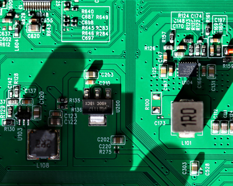
Many manufacturers do not lose money because the component price is too high. They lose it through repeated feeder setup, machine loading, manual handling, low board utilization, poor depanelization, and defects caused by weak or distorted panels.
A single small PCB may occupy only 20% of the placement machine’s usable area. If the same design is assembled as a four-up or eight-up panel, the machine can place components on several boards during one program cycle. The result is usually fewer conveyor transfers, fewer board-loading actions, and a lower assembly cost per finished PCB.
However, “larger panel” does not automatically mean “lower cost.” A panel that exceeds the placement machine’s maximum size, bends during reflow, blocks tooling holes, or creates excessive stress during routing can reduce first-pass yield. The correct target is the best balance between panel utilization, machine compatibility, component density, depanelization method, and quality risk.
PCB Panelization for SMT Assembly Efficiency: What Problem Does It Solve?
- Panel utilization: the percentage of the manufacturing panel covered by usable PCB area.
- Board count per panel: the number of repeated circuit boards in one array.
- Assembly cycle time: the time required to load, place, inspect, and unload one panel.
- First-pass yield: the percentage of boards that pass inspection without rework.
- Depanelization cost: the labor, tooling, and machine time required to separate individual boards.
- Panel rigidity: the ability of the array to remain flat during printing, placement, and reflow.
A useful cost model is:
Assembly cost per PCB = (panel setup cost + panel processing cost + inspection cost + depanelization cost + rework cost) ÷ good PCBs produced.
This equation explains why a panel with eight boards can be more expensive than a four-board panel if it produces more solder defects or requires slow manual separation.
PCB Panel Design for Low-Cost Manufacturing: The Main Variables
The answer depends on the smallest board dimension, the assembly line’s working area, component overhang, tooling requirements, and the selected separation process. A common starting point is to design a panel that fits the SMT line’s standard board range, often approximately 50 × 50 mm to 460 × 460 mm, although the exact limits vary by printer, mounter, reflow oven, and conveyor system.
How Many PCBs per Panel? A Practical Selection Method
Use the following calculation before creating the array:
- Measure the finished PCB: record its length, width, thickness, component height, and edge-clearance requirements.
- Confirm equipment limits: obtain the actual maximum and minimum panel dimensions from the solder-paste printer, placement machine, AOI system, reflow oven, and depanelizer.
- Reserve the border: leave approximately 5–10 mm of tooling rail where the equipment requires it. The final value must follow the assembly supplier’s specification.
- Calculate the array: test 2-up, 4-up, 6-up, 8-up, or larger arrangements without exceeding the machine envelope.
- Compare yield-adjusted output: do not compare only the number of boards. Compare the number of good boards produced per hour.
For example, assume one PCB requires 18 seconds of placement time when processed individually. A four-up panel may not require 72 seconds because feeders and board handling are shared. If the complete panel cycle takes 48 seconds, the theoretical output is 4 boards every 48 seconds, or 300 boards per hour before downtime and defects. If the first-pass yield is 98%, the good output is approximately 294 boards per hour.
By contrast, an eight-up panel may take 82 seconds because of longer travel paths and more inspection data. Its theoretical output is approximately 351 boards per hour before downtime, but if panel flex reduces first-pass yield to 94%, good output falls to about 330 boards per hour. The eight-up design still performs better in this example, but the gain is only about 12%, not 100%.
How Many PCBs per Panel for a Stable SMT Assembly Line?
PCB Panelization for SMT Assembly Efficiency: Benefits and Trade-Offs
SMT production includes several fixed activities: loading the program, installing feeders, verifying component reels, setting stencil parameters, calibrating vision systems, and running the first article. If a production order contains 1,000 individual boards, processing them in larger panels can reduce the number of conveyor loading events and board registration operations.
Panelization is especially valuable when:
- the PCB is physically small;
- the order quantity is medium or high;
- the design is repeated without variations;
- the assembly line supports panel handling;
- the selected depanelization method is already available.
PCB Panel Design for Low-Cost Manufacturing Reduces Setup Cost
Small boards are difficult to place manually on conveyors and may be rejected by board-support systems. A rigid panel gives the printer and placement machine a larger reference surface. It also reduces the chance that an operator drops, rotates, or misaligns individual boards during transfer.
Panel rails can include tooling holes, global fiducial marks, barcode locations, and support points. These features help maintain repeatable registration between the stencil, PCB copper pattern, and component placement coordinates.
PCB Panel Design for Low-Cost Manufacturing Improves Handling
Panelization introduces additional design features that are not part of the final product. These include mouse-bite perforations, routed grooves, V-score lines, rails, tabs, tooling holes, and fiducials. Each feature can affect production.
- V-score problems: insufficient residual material may cause premature separation; excessive residual material may increase operator force and edge damage.
- Routing-tab problems: tabs may leave sharp edges or create visible stress marks.
- Panel bow and twist: uneven copper distribution or a large unsupported area can cause printing and placement errors.
- Component clearance problems: tall parts near the separation line may collide with neighboring boards or the depanelizer.
- Thermal imbalance: different copper densities across the array can create uneven heating during reflow.
PCB Panelization for SMT Assembly Efficiency Can Increase Risk
PCB Panelization for SMT Assembly Efficiency: Required Preparation
Prepare the following information before asking a fabricator or assembler to create a panel:
- PCB fabrication data: Gerber or ODB++ files, drill files, board outline, copper layers, solder mask, silkscreen, and paste layers.
- Assembly data: centroid or pick-and-place file, bill of materials, assembly drawing, polarity information, and approved manufacturer list.
- Mechanical data: finished board thickness, allowable bow and twist, component heights, keep-out zones, connector overhang, and enclosure restrictions.
- Production data: target quantity, required delivery date, expected annual volume, and whether the board will be assembled on both sides.
- Quality data: IPC class, inspection requirements, acceptable defect criteria, and whether traceability labels are needed.
PCB Panel Design for Low-Cost Manufacturing Materials and Files
Useful tools include PCB CAD software, a mechanical drawing program, Gerber viewers, a panelization utility, a design-rule checker, and the SMT supplier’s equipment capability sheet. A 2D or 3D mechanical review is important when the panel contains connectors, switches, heat sinks, shields, or components taller than approximately 10–15 mm.
Ask the assembly supplier to confirm:
- maximum and minimum panel dimensions;
- maximum panel weight;
- acceptable board thickness;
- minimum rail width;
- fiducial size and clearance;
- tooling-hole diameter and location;
- minimum component-to-edge clearance;
- supported V-score and routing specifications;
- depanelization equipment and maximum panel thickness.
PCB Panelization for SMT Assembly Efficiency Tools
Step-by-Step PCB Panelization for SMT Assembly Efficiency
Lock the final PCB outline before duplicating the design. Confirm whether connectors, test points, mounting holes, and switches extend beyond the board edge. A board outline that changes after panelization can invalidate the stencil, pick-and-place coordinates, and mechanical drawing.
Place copper pours and sensitive components consistently across each repeated board. If one board has substantially more copper than another, the panel may heat unevenly during reflow.
Step 1: PCB Panel Design for Low-Cost Manufacturing Starts with the Finished Outline
Create at least three alternatives, such as 2-up, 4-up, and 6-up. Compare the following values:
| Measure | 2-up example | 4-up example | 6-up example |
|---|---|---|---|
| Boards per panel | 2 | 4 | 6 |
| Estimated panel cycle | 30 seconds | 46 seconds | 68 seconds |
| Theoretical boards/hour | 240 | 313 | 318 |
| Assumed first-pass yield | 99% | 98% | 95% |
| Approximate good boards/hour | 238 | 307 | 302 |
This example shows why the largest array is not always the best array. The six-up panel carries more boards, but its lower yield makes it slightly less productive than the four-up option.
Step 2: How Many PCBs per Panel Should Be Tested in CAD?
Add rails where the printer and placement machine require them. Rails provide space for conveyor clamps and help prevent the PCB edge from contacting components.
Use global fiducial marks for panel-level alignment and local fiducials near fine-pitch packages when required. A typical fiducial is a copper circle exposed through the solder mask, often around 1 mm in diameter, with a clear area around it. The exact dimensions should follow the assembly machine’s specification.
Keep fiducials free from silkscreen, solder mask openings that are too large, copper patterns, labels, and nearby perforations. A dirty or partially covered fiducial can reduce vision-system recognition and cause placement offsets.
Step 3: PCB Panel Design for Low-Cost Manufacturing Adds Rails and Fiducials
V-score creates a straight groove on the top and bottom surfaces of the PCB. It is suitable for straight board edges and generally supports rapid separation. It is less suitable when the board outline contains curves, internal cutouts, or irregular shapes.
Routing with breakaway tabs uses a router to cut around the board outline while leaving small tabs. It supports irregular outlines but may create burrs, dust, and localized mechanical stress. Mouse-bite perforations can be added to the tabs, although the remaining edge may require sanding or trimming.
As a practical starting point, keep sensitive components at least 2–3 mm from a V-score or routed edge unless the assembler approves a smaller distance. Increase the clearance for ceramic capacitors, large MLCC arrays, glass-bodied components, and connectors that may be damaged by bending.
Step 4: PCB Panelization for SMT Assembly Efficiency Selects V-Score or Routing
Add tooling holes, support rails, and breakaway features without interfering with the product outline. For thin boards or large panels, evaluate support pins under areas with heavy components. A board that sags by even a fraction of a millimeter during solder-paste printing can change paste volume and create insufficient or excessive deposits.
For double-sided assembly, confirm that bottom-side components will not collide with support tooling or the conveyor. Also check whether heavy parts on the first side require adhesive, special reflow handling, or an alternative assembly sequence.
Step 5: PCB Panel Design for Low-Cost Manufacturing Includes Support Features
Send the proposed panel drawing, Gerber panel file, assembly panel file, and depanelization notes to the manufacturer. Request a design-for-manufacturing review before ordering the stencil or production quantity.
Benewave, for example, can review the relationship between the panel outline, SMT equipment, stencil openings, fiducials, and separation method before production. The important point is not the brand name; it is obtaining written confirmation that the proposed panel fits the complete manufacturing route.
Step 6: PCB Panelization for SMT Assembly Efficiency Requires a Manufacturing Review
Real Production Case: PCB Panel Design for Low-Cost Manufacturing
An anonymized production record from a small controller board project illustrates the effect of panelization. The finished board measured approximately 42 × 58 mm, used 0402 passives and a QFN package, and was initially assembled as a single board. The factory reported frequent manual loading and an assembly price of approximately $0.42 per board at a 2,000-board order quantity.
The engineering team tested a four-up panel with 8 mm rails, two global fiducials, local fiducials near the QFN, and routed breakaway tabs. The panel reduced board-loading operations by approximately 75%. Placement throughput increased from about 220 good boards per hour to 305 good boards per hour after the first article was approved.
The first version of the four-up design placed a ceramic capacitor only 1 mm from the routed edge. During mechanical separation, 7 of 500 boards showed cracked capacitor bodies. The team moved the component 3 mm inward and changed the tab positions. In the next 1,000-board run, no capacitor cracks were recorded, and first-pass yield improved from 96.8% to 98.7%.
The final assembly price fell to approximately $0.31 per board. The saving was not caused only by placing four boards at once. It came from the combined effect of reduced handling, improved machine utilization, fewer separation defects, and a higher number of good boards per panel. This is the type of yield-adjusted calculation that should be used when comparing PCB panel options.
Common PCB Panelization for SMT Assembly Errors and Solutions
PCB Panel Design for Low-Cost Manufacturing Error: The Panel Is Too Large
Symptom: the panel fits the printer but cannot pass through the placement machine or reflow oven.
Solution: confirm the maximum dimensions of every machine in the line, not only the first machine. Include rails, tooling holes, and overhanging components in the measured size.
PCB Panelization for SMT Assembly Error: Missing Fiducials
Symptom: the machine cannot reliably locate the array, or placement offsets vary between repeated boards.
Solution: add panel fiducials at known locations and local fiducials for fine-pitch or high-density areas. Keep them free of copper, silkscreen, solder mask contamination, and routing dust.
PCB Panel Design for Low-Cost Manufacturing Error: Components Are Too Close to the Edge
Symptom: cracked MLCCs, damaged connectors, solder bridging near the edge, or interference with the depanelizer.
Solution: move fragile components inward, increase edge clearance, rotate components to reduce bending stress, and confirm the separation direction with the assembler.
PCB Panelization for SMT Assembly Error: Incorrect V-Score Depth
Symptom: the panel breaks during printing, or excessive force is required during separation.
Solution: request a cross-section or supplier specification for the remaining web thickness. Validate the selected depth on sample panels before mass production.
PCB Panel Design for Low-Cost Manufacturing Error: Poor Copper Balance
Symptom: panel warpage, uneven solder joints, tombstoning, or reflow temperature differences between array positions.
Solution: review copper distribution, add copper balancing where electrically acceptable, avoid large isolated copper differences between repeated boards, and verify the reflow profile with thermocouples.
How Many PCBs per Panel Error: Choosing the Maximum Count Without a Trial
Symptom: the theoretical output is high, but actual good-board output is low.
Solution: run a first-article or pilot batch. Record panel cycle time, solder-paste defects, placement defects, AOI defects, rework minutes, depanelization damage, and final yield. Select the panel with the highest number of good boards per hour, not the highest board count.
PCB Panelization for SMT Assembly Efficiency: Cost Calculation Example
Assume the following production data:
- Order quantity: 10,000 good PCBs
- Single-board setup and handling cost: $0.08 per board
- Four-up panel setup and handling cost: $0.035 per board
- Single-board first-pass yield: 98.0%
- Four-up panel first-pass yield: 98.7%
- Depanelization cost for the four-up panel: $0.012 per board
For single-board assembly, approximately 10,205 boards must be processed to obtain 10,000 good boards at a 98% yield. For the four-up panel, approximately 10,132 boards must be processed at a 98.7% yield. The panel option avoids roughly 73 additional board assemblies and reduces the handling cost on every processed board.
The final quotation should also include stencil changes, panel tooling, test fixtures, inspection time, rework, packaging, and scrap. A supplier that quotes only the machine placement charge may hide the cost of a difficult panel design in later operations.
PCB Panel Design for Low-Cost Manufacturing: Final Recommendations
Start with the assembly line’s real constraints, then create several panel alternatives. For most small and medium PCBs, a four-up panel is a useful initial trial because it often improves handling without creating the mechanical and thermal risks of a very large array.
Use V-score for straight outlines and high-volume separation when edge stress is acceptable. Use routed breakaway tabs for irregular outlines, but inspect the separated edge and protect fragile components from bending loads. Add panel and local fiducial marks, maintain adequate rail width, verify component clearances, and review board support before releasing the manufacturing files.
Measure panel utilization, panel cycle time, first-pass yield, rework rate, depanelization damage, and good boards per hour. In a properly validated PCB panelization for SMT assembly efficiency project, the financial benefit should be visible in production data rather than described with general claims. The most reliable results usually come from a supplier such as Benewave reviewing fabrication, assembly, inspection, and separation as one connected process.
PCB Panelization for SMT Assembly Efficiency FAQ
How many PCBs should be placed on one panel?
There is no universal number. Start with 2-up, 4-up, and 6-up options, then select the design that produces the highest number of good boards per hour while remaining within machine size, rigidity, fiducial, and depanelization limits.
Does panelization always reduce SMT assembly cost?
No. Panelization normally reduces handling and setup cost, but a poorly designed panel can increase solder defects, board warpage, depanelization damage, and inspection time. The correct comparison uses total cost divided by good boards produced.
What is the difference between V-score and routed tabs?
V-score uses straight grooves to create a controlled break line. Routed tabs use a router to cut most of the outline while leaving connecting tabs. V-score is efficient for straight edges; routing is more flexible for irregular outlines.
How much clearance should components have from a panel edge?
A common starting point is 2–3 mm for components near V-score or routed edges, but the required clearance depends on the component type, board thickness, separation equipment, and stress level. Fragile MLCCs and connectors may need more clearance.
Why are fiducial marks needed on a PCB panel?
Fiducial marks provide optical reference points for solder-paste printing and component placement. They help the machine correct for panel position, rotation, and dimensional variation.
Can a PCB panel contain different board designs?
Yes, mixed panels are possible, but they require compatible thickness, solder-paste requirements, assembly side, component technology, and production quantities. Mixed panels may complicate traceability, inspection programming, and depanelization.
What data should be requested from the SMT supplier?
Request the equipment size limits, recommended rail width, fiducial specifications, allowable board thickness, tooling-hole requirements, component edge-clearance rules, supported separation methods, panel weight limit, and expected yield assumptions.
What is the most important panelization metric?
The most useful metric is usually good boards per hour, supported by first-pass yield and total cost per good PCB. Board count per panel alone does not show whether a design is efficient.







