
Phone: +86-137 5102 2384
Phone: +86-137 5102 2384
Jul. 07, 2026
Share:
A robot is fundamentally an integration challenge: it must perceive its environment through sensors, process information in real time, and act upon the world through electromechanical systems—all while moving, vibrating, and interacting with unpredictable surroundings. At the center of this integration sits the printed circuit board assembly (PCBA). Whether embedded in the joint of a six-axis industrial arm, the navigation stack of an autonomous mobile robot (AMR), or the fingertip of a humanoid hand, the PCBA functions as the robot's nervous system.
Unlike consumer electronics, where the primary design constraint is miniaturization, or automotive, where the focus is on environmental hardening, robotics presents a unique convergence of demands: high-speed signal processing, high-current power delivery, and extreme mechanical resilience must coexist in compact, often moving, form factors. A single assembly defect—a cold solder joint on a motor encoder line, a void under a BGA processor, or a delaminated trace in a flexing robot joint—can cause erratic motion, sensor dropout, or catastrophic system failure.
This convergence makes custom PCB assembly for robotics a specialized discipline, not a commodity service.
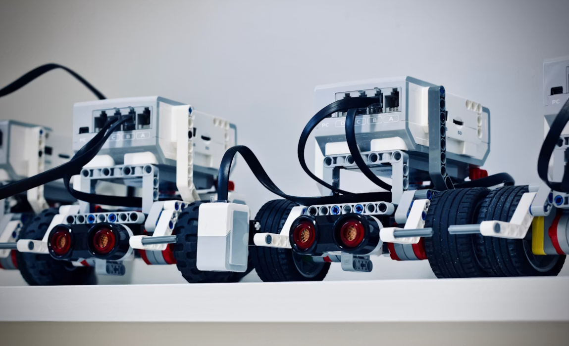
Robotic motion control operates on millisecond—or even microsecond—latencies. A collaborative robot arm processing force-torque sensor feedback at 1 kHz cannot tolerate signal jitter or dropped packets. Similarly, an AMR fusing LiDAR point clouds with camera frames for SLAM (Simultaneous Localization and Mapping) requires multi-gigabit interfaces (MIPI CSI-2, PCIe, 10G Ethernet) with strict impedance control.
High-speed differential pairs: Encoder signals, camera interfaces, and EtherCAT industrial communication require controlled 100 Ω or 120 Ω differential impedance with matched trace lengths (typically ±5 mils) to prevent skew-induced errors.
Isolated analog front-ends: Force sensors, current sensors, and tactile arrays generate microvolt-level signals in the presence of kilowatt-level motor switching noise. PCB assemblies must maintain galvanic isolation (digital isolators, isolated DC-DC converters) and guard-ring layouts to protect sensitive analog traces.
Kelvin sensing: Motor driver PCBs use four-terminal (Kelvin) connections to measure phase current accurately without voltage drop errors from high-current paths—a layout detail that standard assembly shops often overlook.
Robots are electromechanical systems, and motors are their muscles. Servo drives, brushless DC (BLDC) controllers, and stepper motor drivers generate significant heat and electrical noise:
Thick-copper power stages: Motor driver PCBs commonly use 3–6 oz copper for phase current paths carrying 10–50A continuous. This requires step-stencil solder paste printing and reflow profiles that can handle the thermal mass disparity between heavy copper planes and fine-pitch gate driver ICs.
Wide-bandgap semiconductors: SiC MOSFETs and GaN HEMTs are increasingly used in high-performance servo drives for faster switching and higher efficiency. Assembly requires specialized thermal interface materials (sintered silver, phase-change pads) and precise gate-loop inductance control to prevent destructive voltage overshoot.
Integrated power and control: Modern robot joint modules (e.g., harmonic drive actuators with integrated electronics) place a 48V motor driver, a 24V logic supply, and a safety microcontroller on a single board. This creates creepage and clearance challenges that demand careful layout and insulation barriers.
Unlike stationary industrial controllers, robot PCBs live in motion:
Continuous vibration: Industrial robots and mobile platforms experience random vibration profiles (5–500 Hz, per IEC 60068-2-64). Heavy components—electrolytic capacitors, transformers, and large connectors—must be mechanically secured with adhesive staking, clinching, or brackets to prevent pad lifting and solder fatigue.
Flex and bend cycles: Cables between robot links and rotating joints are increasingly replaced by rigid-flex or flex-rigid PCB assemblies. These require specialized fixturing during SMT to maintain planarity, as well as coverlay openings and adhesive control to prevent via fracture during flexing.
Shock resistance: AMRs navigating warehouse floors encounter impacts and bumps. BGAs and CSPs may require underfill (capillary or no-flow) to reinforce solder joints against mechanical shock.
A modern robot is a sensor platform. The PCB assembly must accommodate diverse interfaces:
LiDAR and depth camera interfaces: High-speed FPD-Link or GMSL serializers/deserializers require controlled-impedance coax or shielded differential pairs with proper via stitching and ground referencing.
Tactile and force sensors: Arrays of capacitive or piezoresistive taxels require high-channel-count analog multiplexing and ultra-low-noise power supplies (LDOs with high PSRR).
IMU and gyroscope integration: MEMS inertial measurement units are sensitive to board stress and temperature gradients. Placement must avoid high-flexure zones, and solder reflow profiles must not exceed the device's maximum peak temperature (typically 260°C for 30 seconds maximum).
Robot controllers with high-speed processors (ARM Cortex-A78, NVIDIA Jetson, Intel Atom) and industrial Ethernet switches require laminates that maintain dielectric stability under thermal load:
High-Tg FR-4 (Tg ≥ 170°C): Standard for general control boards exposed to enclosed actuator heat.
Mid-loss materials (e.g., Panasonic Megtron 6, Isola I-Tera MT40): Used for high-speed digital backplanes and vision processing modules where signal rise times are sub-100 ps.
Robot joints, end-effectors, and wearable exoskeletons increasingly use rigid-flex constructions:
Dynamic flex applications: Cables flexing thousands of times per day (e.g., inside a robot wrist) require rolled-annealed (RA) copper on polyimide with bend-radius-controlled design (typically 10× the board thickness for dynamic flex).
Static flex transitions: Rigid-flex boards that bend once during installation (e.g., connecting a motor driver to a control board across a joint) can use electrodeposited (ED) copper but still require adhesiveless constructions for reliability.
High-power motor drives and LED illumination modules in vision systems generate concentrated heat:
Aluminum-backed IMS: Provides thermal spreading for motor driver MOSFETs without the weight and cost of full copper coins.
Direct Bond Copper (DBC) on ceramic: Used in high-power servo modules where junction temperatures exceed 150°C and standard FR-4 would degrade.
Robot controllers integrate dense processing and memory:
Fine-pitch BGA and CSP: 0.4–0.5 mm pitch processors require nitrogen reflow, 3D X-ray inspection for void analysis, and controlled warpage management to prevent corner solder opens.
0201 and 01005 passives: Wearable robotics and compact joint modules use ultra-small passives, demanding placement accuracy of ±25 µm and solder paste volume control within ±10%.
Package-on-Package (PoP): Some compact robot vision modules stack DDR memory atop the application processor, requiring precise flux dipping and placement force control.
Robot PCBs are rarely pure SMT. They combine:
High-current through-hole connectors: Battery interfaces, motor phase terminals, and emergency stop (E-stop) connectors require mechanical robustness that SMT cannot provide. Selective wave soldering or robotic selective soldering ensures reliable barrel fill without exposing nearby fine-pitch components to wave solder temperatures.
Press-fit pins: Backplanes in large industrial robot controllers use press-fit connectors for signal and power distribution, eliminating solder joint fatigue but requiring precise hole tolerance and insertion force monitoring.
Hardware and mechanicals: Standoffs, thermal gap pads, and shielding cans must be placed with the same precision as electrical components, often requiring custom nozzles on placement machines.
Robots operate in harsh environments—factory floors with cutting oil mist, warehouses with dust, and surgical suites requiring sterilization:
Conformal coating: Acrylic, polyurethane, or silicone conformal coatings protect against moisture and particulate ingress. Application must avoid coating optical sensor apertures, connector mating surfaces, and thermal interface areas.
Potting and encapsulation: Motor driver modules in mobile robots are often potted in thermally conductive epoxy to provide vibration damping, thermal transfer, and IP67 environmental sealing. Vacuum degassing is essential to eliminate voids that could cause localized overheating.
Staking and bonding: Large electrolytic capacitors and power inductors receive adhesive staking (typically epoxy or UV-cure acrylic) to prevent mechanical resonance from fracturing solder joints.
Standard ICT and AOI are necessary but insufficient for robotics. The assembly partner must provide application-specific validation:
Robot controller PCBAs are tested with simulated loads:
Motor drive FCT: Each phase is loaded with inductive or resistive banks to verify PWM generation, current sensing accuracy, and overcurrent protection trip points.
Encoder feedback loop test: Simulated quadrature or BiSS-C encoder signals verify that the processor correctly interprets position and velocity data without dropped counts.
Communication stress test: EtherCAT, CANopen, or PROFINET interfaces are tested under full bus load to verify signal integrity and protocol conformance.
Vibration testing: Random vibration per IEC 60068-2-64 or sinusoidal sweep per IEC 60068-2-6 validates mechanical robustness of heavy components and BGA joints.
Thermal cycling: -40°C to +85°C (or +105°C for industrial-grade) cycling reveals solder joint fatigue, delamination, and component parameter drift before field deployment.
EMC pre-compliance: Conducted emissions and radiated emissions testing ensures that motor switching noise does not interfere with wireless localization or safety sensor operation.
For collaborative and medical robots, safety-critical circuits require dedicated verification:
STO (Safe Torque Off) path test: Verifies that the safety relay or safety MCU can de-energize motor drives within the specified safety reaction time (typically <1 ms for cobots per ISO/TS 15066).
Redundancy check: Dual-channel encoder inputs and cross-monitored safety outputs are tested to confirm fault detection capability.
These systems prioritize 24/7 reliability and long service life (typically 10+ years):
Modular joint electronics: Each joint contains a servo drive, encoder interface, and safety brake controller. Assembly must ensure thermal management in a sealed joint housing with no airflow.
Cable management: Internal wiring to moving joints is increasingly replaced by rigid-flex PCB assemblies that eliminate connector failure points.
Cobots work alongside humans without safety cages, placing extreme demands on sensor and control reliability:
Force-torque sensor integration: Six-axis force sensors at the wrist or base require ultra-low-noise analog conditioning with 24-bit ADC resolution. Assembly cleanliness and grounding are critical.
Power-limiting control: The control PCBA must execute force-limiting algorithms in real time. Any latency caused by poor signal integrity or power supply noise can create a safety hazard.
Certification alignment: Assembly documentation must support ISO/TS 15066 (collaborative robot safety) and ISO 13849 (control system safety) certification submissions.
Mobile platforms integrate navigation, power management, and wireless communication:
Battery management systems (BMS): Li-ion or LiFePO₄ battery packs require BMS PCBAs with cell balancing, temperature monitoring, and ISO 13849-compliant safety disconnects.
Navigation sensor fusion: LiDAR, cameras, ultrasonic arrays, and UWB anchors require multiple high-speed interfaces on a single navigation PCBA, demanding careful routing to prevent crosstalk.
Wireless coexistence: Wi-Fi (2.4/5/6 GHz), 4G/5G, and proprietary ISM-band radios must coexist without desensitizing GPS receivers—a layout and shielding challenge.
The emerging humanoid sector pushes integration density to extremes:
Joint actuator integration: Each of 30+ degrees of freedom may contain a custom servo module with integrated motor, gearbox, encoder, and driver electronics. The PCBA must fit within a 40–60 mm diameter cylinder.
Tactile sensing: Fingertip PCBAs integrate pressure, temperature, and proximity sensors with haptic feedback actuators, requiring micro-SMT and micro-assembly capabilities.
Thermal management: With dozens of actuators and a central processing unit in a compact torso, liquid cooling or vapor chamber integration with PCB thermal vias becomes necessary.
These systems demand the highest reliability and regulatory rigor:
ISO 13485 compliance: The assembly facility must maintain medical device quality management systems with full traceability and validated processes.
Sterilization compatibility: PCBAs may be exposed to autoclave steam, gamma irradiation, or ethylene oxide. Material selection (substrate, coating, components) must survive these cycles without degradation.
Fail-safe design: Single-fault condition analysis requires redundant sensors and independent safety monitoring circuits with physically separated PCB layouts.
Robots are becoming autonomous decision-makers. PCB assemblies now integrate:
AI accelerators: NVIDIA Jetson, Google Coral, or custom ASICs for on-device inference, requiring high-speed memory (LPDDR5, GDDR6) and power delivery networks capable of handling 50A+ transient loads.
Sensor fusion hubs: Centralized processing of camera, LiDAR, and radar data on a single PCBA demands high-layer-count HDI boards (16+ layers) with multiple impedance-controlled interfaces.
The ROS 2 (Robot Operating System 2) ecosystem and hardware abstraction trends are driving:
Standardized compute modules: SoM (System-on-Module) carriers that allow robot developers to swap processors without redesigning the entire baseboard.
Interoperable power and communication backplanes: DIN-rail or custom backplane standards for industrial robot cells, requiring press-fit backplane assembly and hot-swap controller design.
Advanced robotics assembly partners are adopting:
Digital twin process simulation: Modeling reflow profiles, placement sequences, and test coverage virtually before physical builds, reducing NPI time by 30–40%.
AI-driven defect prediction: Machine learning on AOI and SPI data predicts latent defects (e.g., early-stage solder joint fatigue) before they become field failures.
Repairable module design: Robot OEMs are designing PCBAs for field replaceability rather than full-system replacement, influencing connector selection and modular layout.
Halogen-free and recyclable materials: Transitioning to halogen-free laminates and lead-free high-reliability solder alloys (e.g., SAC305 with dopants) to meet EU RoHS and emerging right-to-repair regulations.
Custom PCB assembly for robotics is not simply a manufacturing service—it is an engineering partnership. The unique convergence of high-speed digital processing, high-current power electronics, and extreme mechanical stress in robotic systems demands an assembly provider who understands motion control architectures, sensor interfaces, and functional safety requirements.
From the motor driver in an industrial arm to the tactile sensor in a humanoid fingertip, every solder joint, every impedance-controlled trace, and every conformal coating application contributes to whether a robot performs reliably or fails at the moment of truth. As robots transition from programmed automatons to autonomous, AI-enabled collaborators, the sophistication of their PCB assemblies must advance in parallel. Choosing the right assembly partner—one with deep robotics expertise, advanced mixed-technology capabilities, and rigorous application-specific testing—is not a procurement decision. It is a strategic engineering decision that determines whether a robot concept becomes a reliable product.
Robotics assembly differs in three critical dimensions: (1) Mechanical resilience—robots experience continuous vibration, shock, and flexing, requiring component staking, underfill, and rigid-flex expertise; (2) Electrical diversity—a single robot PCBA may combine 0.4 mm-pitch BGA processors with 6 oz copper motor drivers and high-voltage safety circuits, demanding mixed-technology assembly capabilities; and (3) Real-time performance—encoder feedback, force sensor data, and motor control signals require strict signal integrity and isolation that consumer boards rarely need.
Rigid-flex assemblies replace wire harnesses in robot joints, wrists, and rotating axes. They eliminate connector failure points, reduce weight, and improve reliability in motion. However, they require specialized assembly fixturing to maintain planarity during SMT, controlled bend-radius design (typically 10× board thickness for dynamic flex), and adhesiveless constructions to prevent via fracture during repeated flex cycles.
Beyond standard AOI and ICT, motor driver boards require: (1) Loaded functional testing—verifying PWM output, current sensing accuracy, and overcurrent protection with actual inductive loads; (2) Thermal imaging under load—identifying hotspots from poor solder joints or insufficient heatsink contact; (3) Vibration testing (IEC 60068-2-64)—ensuring heavy capacitors and power components survive mechanical stress; and (4) EMC pre-compliance—confirming that switching noise does not interfere with encoder or communication signals.
Collaborative robots must comply with ISO/TS 15066 (collaborative robot safety requirements) and ISO 13849-1 (control system safety). The PCB assembly partner must support PL d / Category 3 or higher safety architectures, which typically require redundant safety channels, galvanic isolation for STO (Safe Torque Off) circuits, and comprehensive documentation for functional safety certification. The facility should ideally maintain ISO 9001 and familiarity with IEC 62061 or IEC 61508 standards.
Compact joint modules integrate motor drivers, encoders, and brakes in a sealed housing with no airflow. Solutions include: (1) Aluminum-backed IMS or embedded copper coins for localized heat spreading from MOSFETs; (2) Thermally conductive potting compounds that transfer heat to the module housing while providing vibration damping; (3) Optimized thermal via arrays under power devices, filled with conductive epoxy; and (4) Phase-change thermal interface materials between the PCBA and the joint's aluminum housing, ensuring consistent thermal contact despite mechanical tolerances.
Find Partners, Not Just Suppliers
Expert OEM & PCBA manufacturing tailored to your exact specifications. Contact us today to discuss your project and discover a more collaborative way to manufacture.
Get a Fast Quote & Free DFM Review
Related PCB Assembly Service







